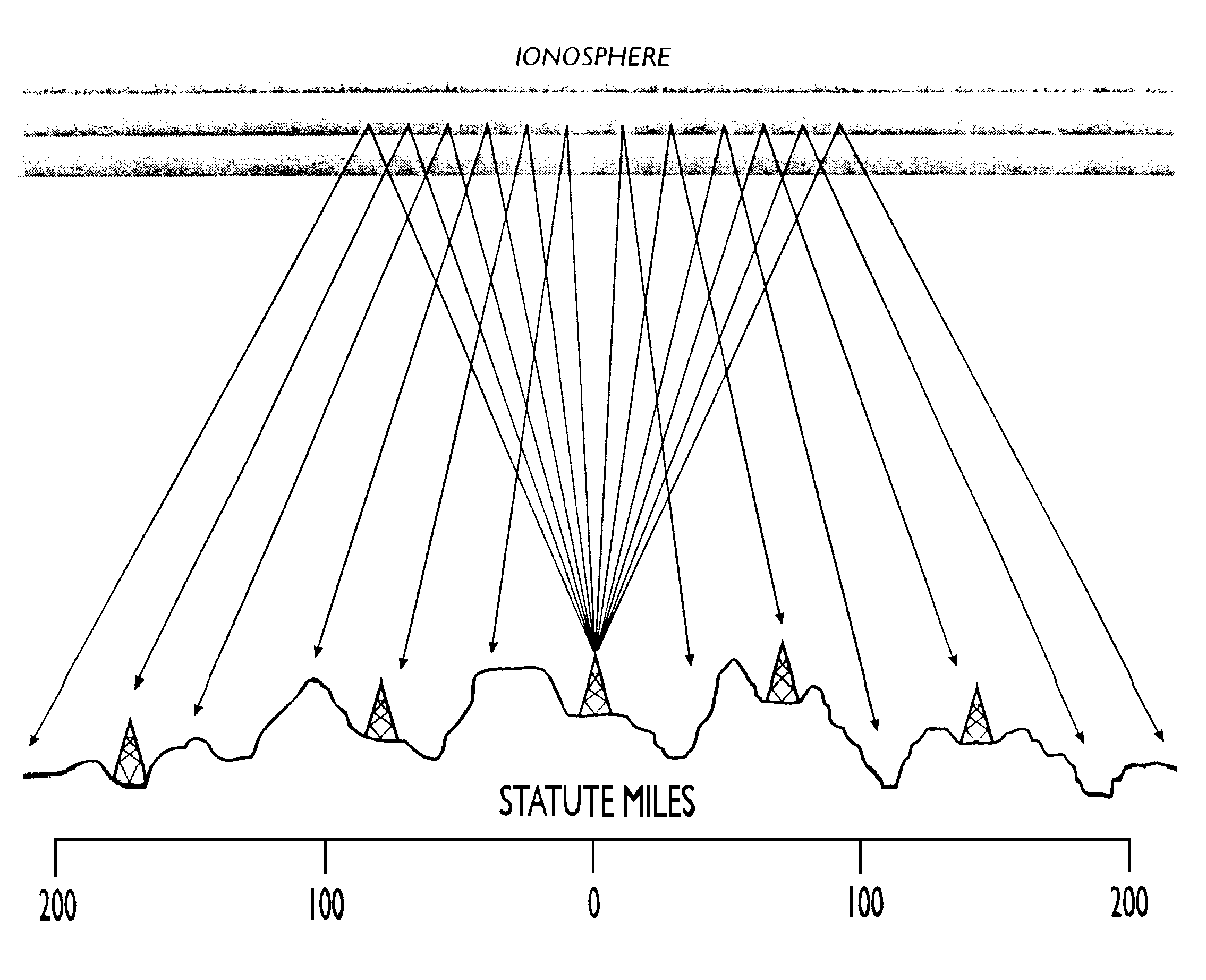
The Near Vertical Incident Skywave (NVIS) antenna is one that provides the majority of its radiation at an extremely high angle. That is to say the major lobe is between 75 and 90 degrees to the earth’s surface. This will provide excellent omni-directional communication out to a distance of 300 to 500 Kilometers. The maximum frequencies involved will be as low as 1.8 Mhz under very poor conditions to as high as 14 Mhz under excellent conditions (which we have not seen in many years), with the most usable being between 3.5 Mhz (80M) and 7.3 Mhz (40M).
Near Vertical Incidence Skywave (NVIS) is a propagation mode which uses high angle radiation to send signals almost straight up to be reflected back to Earth for very effective short to medium distance communications. This mode of operation makes it ideal for in-state communications during disasters or other emergency situations. The military has used NVIS techniques for decades to provide short haul communication with other units on the ground.
The AS-2259/GR is an NVIS (near vertical incident skywave) military antenna for short to medium range communications on the lower HF bands. It has been made over the years by several manufacturers, and when available, they are usually somewhat expensive. This is pretty much the same antenna as the Collins 637K-1, the Telex Model 1990, and the Harris RF-1936.
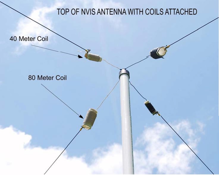
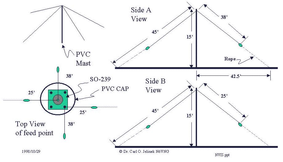
A simple NVIS antenna can be constructed as shown below. This design is thanks to Dr. Carl O. Jelinek N6VNG (SK). In my recontruct of this design I use 4 @ fiberglass “cammo” poles for portable EMCOMM operations rather than a PVC mast. Fiberglass “cammo” are inexpensive and readily available at hamfests. I use a PVC cap to anchor the wires (as shown) at the top of the fiberglass mast.
With a good antenna tuner this antenna will operate over a wide frequency range allowing NVIS operations in a variety of solar conditions.
N3OC also has an excellent description of a similar homebrewed NVIS antenna here.
While a good antenna tuner may be able to match the antenna on 40 and 80 meters, the SWR on the coax feedline is very high, leading to high losses well beyond the matched loss of the coax itself. A quick check with a transmission line program shows that on 3.820 MHz, using 100 ft of RG-8X coax, the high SWR adds 11.6 db of loss on top of the basic 0.4 db matched loss of the coax. The total 12 db of loss means that your 100 watt transmitter is only getting 6.3 watts into the antenna. So why does this antenna work for the military? For one thing, the radio is typically right at the bottom of the mast, not many feet away. Also, for the military version (at least the version built by Collins Radio) the mast itself is designed to be a very low loss, large diameter coax transmission line.
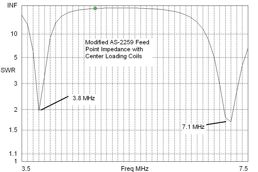
So what can we do to improve this antenna for 40 and 80M amateur use? N3AE and N3IDX have designed modifications to improve operation on 80 and 40 meters. Their web site is here. One solution is to make the antenna elements look longer electrically by adding loading coils near the center of the antenna. EZNEC has a very nice method to add series impedances in the antenna segments. In this case, we need inductive impedance. A bit of trial and error resulted in the much improved SWR plot shown below. At 3.8 MHz, the SWR drops to a respectable 2:1. The 40M SWR is even better, dropping to about 1:1.6 around 7.2 MHz.
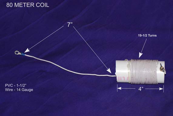
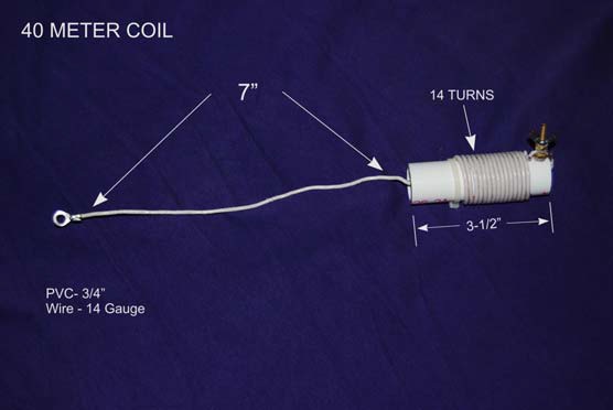
So how do we make the coils? The formula for a single layer closed-wound inductor can be found in the ARRL handbook . The EZNEC derived inductance values were used to build loading coils using PVC pipe for the coil form. The 80M coils use 1.5 inch pipe (which has an outside diameter of 1 7/8 inches). The 40M coils use 3/4 inch pipe (which has an OD of 1.05 inches). Insulated 14 gage house wire was used. After some final tweaking to adjust the number of turns to achieve best SWR as measured by the MFJ-259, we arrived at 14 turns for the 40M coils and 19.5 turns for the 80M coils. The differences between the EZNEC calculated values (19 turns on 40M; 22.5 turns on 80M) and the final MFJ-259 confirmed values are probably due to errors modeling an antenna this close to the ground, plus the fact that the coil wire leads add length to the overall antenna wire.
The coils are close wound on the PVC pipe and anchored by drilling a small hole through the pipe to pass the end of the wire. One end is mounted to a small screw and nut. The coil system easily installs between the antenna’s end cap and the current antenna wire system. 80M and 40M coils are shown below.