Over a period of several months prior to the completion of my attic antenna suite I operated with a borrowed AEA Isoloop antenna. This magnetic loop antenna covers the HF band from 10-30 Mhz. The only current commercial supplier
of a similar loop is MFJ Enterprises MFJ-1786.
I found the loop to be an effective antenna when operated horizontally (horizontal dipole mode) at a reasonable
height above ground (30 ft. in my case). The theoretical pattern is omnidirectional. I found no significant evidence that my pattern
was any different.
Most of my operation with this antenna was QRP (3 watts) PSK using a PSK-20 (Small Wonder Labs, but no longer in business) on 20 meters. During this time I was able to work over 45 countries. I recommend a small magnetic loop when either space is
unavailable for full size antennas or regularly retuning is not objectionable.
My final antenna suite while in the townhouse consisted of 2 sets of HF dipoles and a J-pole
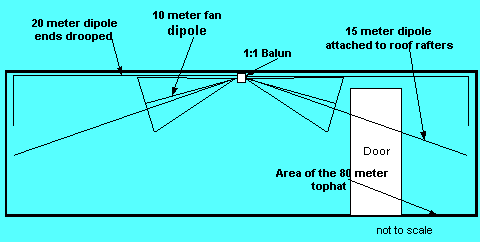
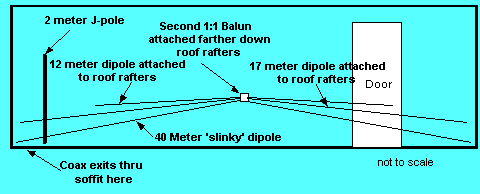
for 2 meter operation. The figures below shows the configuration of
these antennas. These views are looking at the wall of the attic area facing the living space

is used as end insulators. End support is provided by nails into the roof
rafters.
The first dipoles started as standard 20, 15, and 10 meter dipole combination.
All three dipoles were fed from a single 1:1 balun. All dipoles were full size
but as is normal with this kind of configuration they were experimentally
trimmed for resonance within each band. The 20 meter dipole extends the full
length of the space and the last 3 feet or so is drooped vertically at the
end wall. The 20 and 15 meter dipoles worked fine with VSWR under 2:1 across the band. The 10 meter antenna however, was very narrow. To remedy the narrow bandwidth I used a bowtie dipole antenna for 10 meters. My version of the fan was constructed of 1/2 inch copper pipe tee with 14 AWG house wire connecting elements. VSWR is under 2:1 for nearly the entire 10 meter band
The second dipole set (lower on the roof rafters) started as a 40 meter only
“slinky” antenna. This antenna simply uses 2 standard metal slinky toys
connected to a 1:1 balun and stretched to the corners of the attic space.
A non-metallic messenger line provides support for the slinkys. This antenna
is a linear inductively loaded short dipole resonant on 40 meters. Overall, the
on-air performance was ok but certainly not great. It did allow me operation
on 40 meters.
Some literature suggests that this 40 meter half wave slinky can be operated
as a 3/2 wave antenna on 15 meters. I was unable to get an acceptable (<3:1)
VSWR on 15 meters. Thus, I choose to use a separate 15 meter dipole even with
the potential interaction between the antennas.
After setting up the 40 meter dipole, I decided to add WARC band coverage to
my antenna suite. 12 meter and 17 meter dipoles were added to the 40 meter
dipole. Thus, in this limited attic space I now have 6 operating HF bands and
instant band switching!

not critical. The initial dipole length was set by
468 / frequency (Mhz) = Length in feet
The dipoles were then trimmed in INCREASING frequency order i.e. 20m then 15m
then 10m. If at all possible, use of an antenna analyzer such as an MFJ 259 is recommended for
antenna measurements. Using an analyzer changes the trimming task from hours
to minutes (especially important in an attic on a hot summer day) and eliminates radiating test signals.
30 meters was not included for space reasons and I’m not much of a CW operator
anyway.
It should be noted that while many of the dipoles show very good VSWR
it’s not perfect solution. All the antennas have VSWR at or below 2:1 and
all loaded into my TS-570D. Antenna patterns in such close confines of the house and other antennas are not really predictable. My on-the-air experience with low power has been acceptable.
Though my attic antennas were developed on a trial and error basis, antenna modeling can give significant insight into the antenna performance. here is a web site that illustrates how to go about modeling attic antennas. Computer Assisted Low Profile Antenna Modeling
